Inertial stabilization and visual servoing for aerial surveilance
Starting in 2006, for nearly ten years we were involved in a series of R&D projects aimed at development of inertially stabilized airborne camera platforms for aerial surveillance.
The coordinator of the projects was the then Czech Air Force and Air Defense Technological Institute (VTÚLaPVO), which later became a part of the newly established Military Technical Institute (VTÚ s.p.). Other project partners were computer vision specialists from Center of Machine Perception (CMP) FEE CTU (then lead by prof. Václav Hlaváč) and a small mechanical engineering company ESSA located in Prague. Most of the research and development was funded by Ministry of Industry and Trade of the Czech Republic.
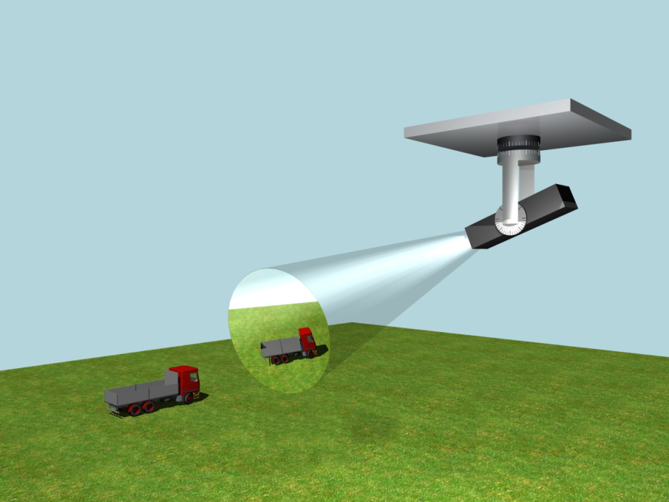
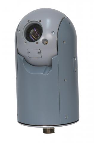
The key task for the platform(s) was to stabilize the line of sight of the optoelectrical payload (day vision camera, infrared camera, laser range finder and laser beamer) in presence of disturbing rotational motions of the carrier (helicopter, unmanned aircraft). On top of the inertial stabilization, automatic image tracking of the ground target was required, which would compensate for the translational motion of the aircraft and/or the ground target.
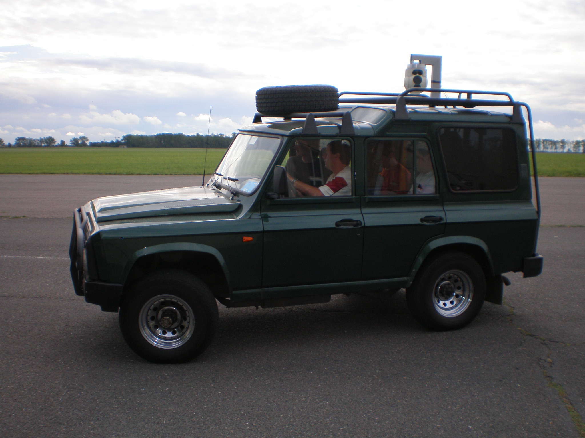
The early prototype finalized in 2008 was based on the classical double-gimbal mechanical configuration, two direct drive DC motors and a three-axis MEMS-based gyro. The prototype was tested extensively in the lab, and also outdoor, carried by a car.

While the mechanical design and prototyping was done by ESSA company and the computer vision system was developed by our colleagues from CMP, our group did all the electronics, instrumentation and control software. Some technical details can be found in the MSc theses Řezáč (2008) and Žoha (2008) (both in Czech).
Concerning the control design, our primary contribution was in systematic combination of the inertial stabilization loop (based on angular rate feedback from the gyros) with the visual servoing loop (based on image feedback from the camera). We described this in the journal paper Hurak and Rezac (2012).
A particular technical challenge we faced was the delay introduced by the computer vision methods. We proposed a few compensation schemes in Hurák and Řezáč (2010).
Although the key sensor for inertial stabilization was a three-axis MEMS gyro (measuring the inertial angular rate round the three body axes), we also used MEMS accelerometers to compensate for fhe disturbing torque induced by combined effect of vibrations and static unbalance of the optoelectrical payload. This we described in the conference paper Řezáč and Hurák (2011).
An extra functionality that we needed in order to relate the motion of the optical payload to the object tracked on the ground was accurate estimate of the orientation of the optical payload. Design and implementation of multisensor fusion based on extended Kalman filter is described in the conference paper Řezáč (2013).
Practical lessons learnt with the first prototype were used to design two more versions: First, a light(er) version that avoided the use of direct drives, but then had to compensate the non-negligible friction. The sensoric part remained the same, i.e., three-axis MEMS gyros This was documented in the thesis Salášek (2012) (in Czech).
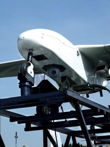
Second, a heavy-duty version, which features four gimbals: two outer gimbals driven by regular DC motors with a belt gear and the two inner gimbals driven by DC voice-coil motors with a limited angle. Furthermore, instead of a MEMS gyro, fiber-optics gyro was used.
In order to facilitate our studying of control of such dual-stage mechanisms, we assembled a laboratory testbed featuring the same configuration, albeit restricted to a single axis only. A rigid plate freely rotatable around a vertical axis carries a standard DC brush-type rotary motor, which via a belt transmission drives the secondary stage carrying a DC voice-coil motor, which pushes the payload. The voice-coil motor enjoys a very small friction, which is a very plausible property for inertial stabilization, but its angular stroke is limited to (+-5 deg). Therefore, the (geared) DC brush-type rotary motor is used to keep the angular deviation close to zero (this is called mid-range control in the industrial process control domain). The key disturbance is the angular velocity of the freely rotatable plate upon which the stator of the DC brushed motor resides. This mimics the unwanted angular motion of a mobile carrier (car, aircraft, ship). The video below can help understand the principle.
Our study of control design for such dual-stage inertially stabilized mechanisms is described in the journal paper Řezáč and Hurák (2013). The paper is accompanied by downloadable Matlab/Simulink code implementing the control design and simulation environment.
And then we were finally ready for some flight experiments.


What we particularly enjoyed about those experiments was that our students (Martin and Jaroslav) had an opportunity to actually participate in these as the operators of the system during the test flights.


A video from one of our demonstration flights, in which we used a helicopter as the carrier is below.
Some more videos are in our dedicated Youtube playlist.
The whole project attracted the attention the Czech Television and one episode of popular science and technology magazine PORT was dedicated to the project in 2022. In the video, which we link below for convenience, we also uncover the device so that the internal structure and functioning can be seen.
At about the time Martin Řezáč was defending his PhD thesis Řezáč (2013), we wrapped up the whole project and passed the deliverables to our partner for further development and possible commercialization. Since then we did not pursue research in the area of inertial stabilization any further.